HIGH SPEED CABLE — TECHNICAL INTRODUCTION
From core signal integrity design and R&D simulation capability to 100% high-frequency final testing, here is the full picture of C.C.P. high speed cable technology and manufacturing strength.
A Direct Attach Cable (DAC) is a direct-connect copper cable solution that carries high-speed differential signals through a precise combination of Pogo Pin, PCBA and high speed cable. Compared with optical modules, a DAC needs no electro-optical conversion, giving it three advantages — low power, low latency and low cost. It is widely used for short-reach interconnects between data center racks, in 5G telecom infrastructure and in enterprise high-performance networks.
The C.C.P. DAC cable series covers both External (SFP / QSFP) and Internal (OCuLink / Slimline SAS / Gen Z / MCIO) types, with data rates from 10Gbps up to custom 400Gbps specifications and full support for the latest PCIe Gen5 protocol.
Product Structure
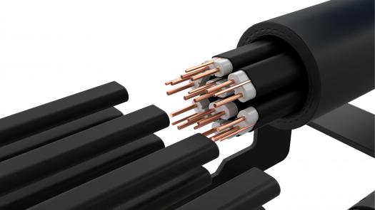
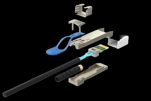
Taking the SFP 25Gbps cable as an example, C.C.P. uses a multi-layer precision material stack with strict material specification control on every part to guarantee signal transmission quality.
Core Technology
The stub effect is the most critical signal integrity problem in high speed cables. When a cable connects to a PCB, any unterminated conductor stub reflects high-frequency signals at its end. C.C.P. eliminates the stub effect completely through a precise Pogo Pin plus cable-cutting process design.
Insertion Loss (SDD21) comparison, 0 – 60GHz
An unterminated conductor stub remains at the cable termination. High-frequency signals reflect at the end of the stub, producing resonant dips at specific frequencies that severely degrade the insertion loss curve.
C.C.P. eliminates the stub entirely through a Pogo Pin spring design plus a precise laser stripping process. The insertion loss curve rolls off smoothly and signal integrity improves substantially.
R&D Capability
C.C.P. has complete hardware and software R&D capability, from 3D high-frequency simulation to physical measurement, so products meet signal integrity requirements at the design stage.
Precise Process Control
Cable signal quality depends not only on design but equally on process precision. C.C.P. has built strict measurement and control systems around three key processes: Mylar stripping, solder quality and laser stripping.
Mylar stripping length precision directly affects cable impedance. Stripping of >0.4mm versus <0.4mm shows a clear difference in TDR measurement, and C.C.P. monitors stripping quality in real time using the TDR waveform.
Irregular solder quality produces clear impedance anomalies in the TDR waveform and causes signal reflection. C.C.P. uses SDD11 return loss as a fast screening indicator of solder quality.
YAG laser precision stripping of the aluminium foil is more accurate than conventional blade stripping. After the inner jacket is stripped, a CO₂ laser performs a second finishing pass so the inner conductor is not damaged and impedance continuity is maintained.
Structural finite element analysis (FEA) with ANSYS simulates cable deformation under bending, tension, thermal cycling and other mechanical stresses, ensuring the physical structure is reliable.
100% High Frequency Testing
Every C.C.P. high speed cable is tested before shipment on a vector network analyzer across the full set of differential and common mode S-parameters, together with long-duration traffic validation on a Spirent Test Center.
Using a Spirent Test Center, traffic was transmitted continuously on two 400Gbps ports for 18 hours with TX and RX packet counts exactly equal and zero traffic loss — verifying long-duration stability at the highest specification and meeting hyperscale data center deployment requirements.
Testing Equipment
Automation Production Line
C.C.P. high speed cables are built on a fully automated production line. From wire positioning and laser foil stripping to PCB placement soldering and UV curing, machine vision and automated equipment replace manual work at every step.
A YAG laser strips the outer aluminium foil from the wire and positions it to ±0.1mm, establishing a consistent reference for the downstream processes.
Automated equipment precisely strips the upper and lower aluminium foil and straightens the wire.
A CO₂ laser precisely strips the jacket from the core wires; after the cores are formed, the outer jacket is stripped so the solder surface is clean and free of residue.
PCB positioning → manual board assembly on a general-purpose machine → solder paste positioning → drag soldering (front) → drag soldering verification (front); after double-sided soldering, optical inspection is performed.
UV adhesive dispensing → UV curing → automated CCD optical inspection, ensuring solder joint appearance and position meet specification, with defective units rejected automatically.
Application Areas
C.C.P. high speed cables are widely used wherever high bandwidth is required, serving the world top technology companies including Apple, Google and Amazon.
Hyperscale data centers need high-density short-reach interconnects between racks and between ToR switches. With low latency and low power consumption, DAC cables are the best alternative to optical modules.
5G base station fronthaul and telecom equipment rooms demand higher weather resistance from cables. C.C.P. cables pass thermal shock, salt spray and other rigorous environmental validation, making them suitable for outdoor and high-density equipment room deployment.
C.C.P. engineers can provide signal integrity analysis reports, custom cable length specifications and small-volume sample service.
